

BGP Peering with Juniper CN2
Author: Motohiro Abe
Introduction
In this blog post, I would like to dive into the implementation of CN2 (Juniper Cloud-Native Container Network) as the Container Networking Interface (CNI) in OpenShift. I will explore the process of establishing BGP (Border Gateway Protocol) peering to make pod network and service IPs visible to an external router, specifically MikroTik Router. Additionally, I will test the external connectivity without a traditional load balancer, leveraging CN2's Fabric Forwarding feature.
Please note that this post will focus on the lab config and testing aspects of CN2 in OpenShift and will not cover the installation process.
Lab topology
The lab topology for this experiment is as follows:
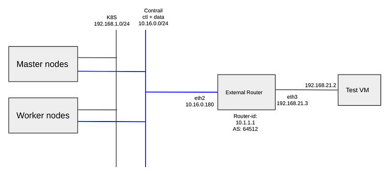
Configuration of Router OS
Start by configuring the Router OS, the MikroTik Router, to establish connectivity with the OpenShift/CN2 cluster.
You can configure the Router OS with the following commands:
/interface bridge add name=lobridge
/ip address add address=10.16.0.180/24 interface=ether2
/ip address add address=10.1.1.1/32 interface=lobridge
/ip address add address=192.168.21.1/24 interface=ether3
/interface bridge port
add bridge=lobridge interface=ether2
add bridge=lobridge interface=ether3
/routing bgp connection
add address-families=ip as=64512 disabled=no local.address=10.16.0.180 role=ibgp name=bgp1 output.redistribute=connected,static remote.address=10.16.0.0/24 as=64512 router-id=10.1.1.1 routing-table=main
Once the configuration is complete, the routing table should appear as follows:
[admin@MikroTik] /ip/address> print
Columns: ADDRESS, NETWORK, INTERFACE
# ADDRESS          NETWORK       INTERFACE
0 10.16.0.180/24   10.16.0.0     ether2
1 10.1.1.1/32      10.1.1.1      lobridge
2 192.168.21.3/24  192.168.21.0  ether3
Configure BGP router on CN2
Now, let's move on to the CN2 configuration. I set up a BGP router CR (Custom Resource) for an external router, which in this case, is the MikroTik router. The configuration involves specifying the external router's IP and identifier in the CR, establishing BGP peering between Contrail Control Node and the external router, and advertising routes from the Contrail Virtual Network to the external router.
Here is the content of the BGProuter CR YAML file:
apiVersion:  core.contrail.juniper.net/v1alpha1
kind: BGPRouter
metadata:
  namespace: contrail
  name: bgprouter
spec:
  parent:
    apiVersion: core.contrail.juniper.net/v1
    kind: RoutingInstance
    name: default
    namespace:  contrail
  bgpRouterParameters:
    vendor: Juniper
    routerType: router
    address: 10.16.0.180   # External Router Address
    identifier: 10.1.1.1    # The Router ID
    holdTime: 60
    addressFamilies:
      family:
        - inet
        - inet-vpn
        - route-target
        - inet6-vpn
    autonomousSystem:  64512
Once the configuration is applied, you can check the CNS2 status.
 $ oc get bgprouter -A
NAMESPACE   NAME        TYPE           IDENTIFIER    STATE     AGE
contrail    bgprouter   router         10.1.1.1      Success   5m34s
contrail    master1     control-node   10.16.0.249   Success   4d23h
contrail    master2     control-node   10.16.0.228   Success   4d23h
contrail    master3     control-node   10.16.0.194   Success   4d22h
On the router, there should be three bgp sessions.
[admin@MikroTik] /routing/bgp/session> print
Flags: E - established
 0 E name="bgp1-1"
     remote.address=10.16.0.194 .as=64512 .id=10.16.0.194 .capabilities=mp,gr .afi=ip,vpnv4 .hold-time=1m .messages=31 .bytes=1027 .eor=""
     local.role=ibgp .address=10.16.0.180 .as=64512 .id=10.1.1.1 .capabilities=mp,rr,gr,as4 .messages=25 .bytes=514 .eor=""
     output.procid=20
     input.procid=20 .last-notification=ffffffffffffffffffffffffffffffff0015030603 ibgp

-- omit ---
Creating a Namespace with IP Forwarding
Now, we can create a namespace with IP forwarding enabled. This configuration allows the IP fabric to be applied to both the default pod network and the default service network within the namespace. I am using isolated-namespace.
Create a namespace with the appropriate label and annotation. In this example, I use the namespace name "ns1" and apply the "ip-fabric" forwarding mode with the label "core.juniper.net/isolated-namespace: true". Use the following YAML configuration:
apiVersion: v1
kind: Namespace
metadata:
  name: ns1
  annotations:
    core.juniper.net/forwarding-mode: "ip-fabric"
  labels:
    core.juniper.net/isolated-namespace: "true"
After creating the namespace "ns1" with IP forwarding, the Virtual Networks (VNs) are created as follows:
NAMESPACE                                    NAME                      VNI    IP FAMILIES   STATE     AGE
contrail-k8s-kubemanager-contrail-contrail   default-externalnetwork   4100   v4            Success   4d13h
contrail-k8s-kubemanager-contrail-contrail   default-podnetwork        4096   v4            Success   5d20h
contrail-k8s-kubemanager-contrail-contrail   default-servicenetwork    4098   v4            Success   5d20h
contrail                                     ip-fabric                 4097                 Success   5d20h
contrail                                     link-local                4099                 Success   5d20h
ns1                                          default-podnetwork        4101   v4            Success   19h
ns1                                          default-servicenetwork    4102   v4            Success   1
- ns1/default-podnetwork: This VN represents the pod network specific to the "ns1" namespace.
- ns1/default-servicenetwork: This VN represents the service network specific to the "ns1" namespace.
Testing!
For simplicity and testing purpose, add the anyuid security constraints to the default service account in the newly created namespace. Run the following command:
oc adm policy add-scc-to-user -n ns1 anyuid -z default
Create pods and a service.
apiVersion: apps/v1
kind: Deployment
metadata:
  name: backend
  namespace: ns1
  labels:
    app: backend
spec:
  replicas: 2
  selector:
    matchLabels:
      app: backend
  template:
    metadata:
      labels:
        app: backend
    spec:
      securityContext:
        runAsUser: 0
      containers:
      - name: backend
        image: nginx:alpine
        ports:
        - containerPort: 80
---
apiVersion: v1
kind: Service
metadata:
  name: backend-svc
  namespace: ns1
spec:
  ports:
  - name: port-80
    targetPort: 80
    protocol: TCP
    port: 80
  selector:
    app: backend
  type: ClusterIP
Verify that pods and service are launched in the "ns1" namespace and check their IP addresses.
$ oc get pod -n ns1 -o wide
NAME                       READY   STATUS    RESTARTS   AGE   IP             NODE      NOMINATED NODE   READINESS GATES
backend-86db9cc55b-4l6gt   1/1     Running   0          41s   10.128.0.54    worker2   <none>           <none>
backend-86db9cc55b-kzxvt   1/1     Running   0          41s   10.128.0.105   worker1   <none>           <none>

$ oc get svc -n ns1
NAME          TYPE        CLUSTER-IP      EXTERNAL-IP   PORT(S)   AGE
backend-svc   ClusterIP   172.30.141.68   <none>        80/TCP    69s
Check the routes in the MikroTik router and ensure that the service and Pod IP addresses are exported correctly.
[admin@MikroTik] /routing/bgp/session> /ip/route/print
Flags: D - DYNAMIC; A - ACTIVE; c, b, y - BGP-MPLS-VPN
Columns: DST-ADDRESS, GATEWAY, DISTANCE
    DST-ADDRESS       GATEWAY      DISTANCE
DAc 10.1.1.1/32       lobridge            0
DAc 10.16.0.0/24      lobridge            0
D b 10.128.0.54/32    10.16.0.155       200
DAb 10.128.0.54/32    10.16.0.155       200
DAb 10.128.0.105/32   10.16.0.195       200
D b 10.128.0.105/32   10.16.0.195       200
D b 172.30.141.68/32  10.16.0.155       200
DAb 172.30.141.68/32  10.16.0.155       200

-- omit --
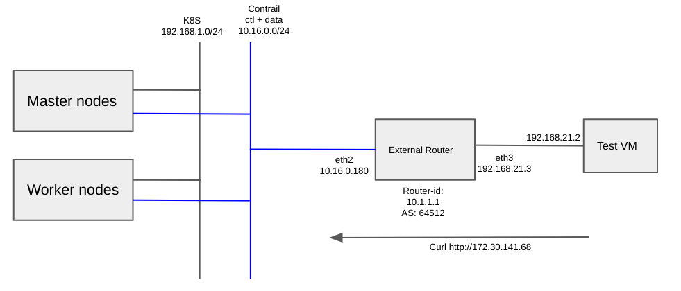
Finally, send a curl request to the service ip from Test VM, verifying the test VM can reach to the service through the external router.
root@testvm:~# curl http://172.30.141.68
<!DOCTYPE html>
<html>
<head>
<title>Welcome to nginx!</title>
<style>
html { color-scheme: light dark; }
body { width: 35em; margin: 0 auto;
font-family: Tahoma, Verdana, Arial, sans-serif; }
</style>
</head>
<body>
<h1>Welcome to nginx!</h1>
<p>If you see this page, the nginx web server is successfully installed and
working. Further configuration is required.</p>

<p>For online documentation and support please refer to
<a href="http://nginx.org/">nginx.org</a>.<br/>
Commercial support is available at
<a href="http://nginx.com/">nginx.com</a>.</p>

<p><em>Thank you for using nginx.</em></p>
</body>
</html>
Conclusion
In this blog, by enabling IP forwarding in the namespace, I applied the IP fabric feature to both the default pod network and the default service network within that namespace. This allowed pods and services in the namespace to communicate with an external router through CN2's fabric forwarding feature.
Integration virtual network with external router brings several benefits. It allows the use of physical routers for external connections to the virtual network, eliminating potential software gateway bottlenecks. It also opens up possibilities for expanding the virtual network to include VPN connectivity with external networks.
In this blog, I just tested a simple scenario to set up the CN2 functionality in a small home lab environment. However, there are many more testing and exploration to further expand on this topics. such as adding MPLS.
References
- Cloud-Native Contrail Networking Feature Guide
- CN2 operation Guide (JP)
- MikroTik RouterOS Documentation